
How to Create a Multi-Pad
Step 1: Goto Mechanical
Design > Part Design….
Step 2: Select
the plane and click of Sketch
Task Environment and it directly takes you to Sketchy Window.
Step 3: Here
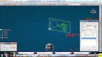
select any Sketch tool to Sketch a Profile; I selected Rectangle, circle Sketch
tool to sketch a profile as shown in images, And given the specified value.
Then Exit
Sketch Task Environment
Step4: Now
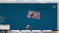
select the Multi-Pad icon and give the specified value here I gave different
thickness value by individually selecting the profile sketch then click on OK.
Finally Multi-Pad part is created.
Refer Images


0 comments:
Post a Comment